

Some Thoughts on a Dual-Uplink Non-Stacking Network Architecture
Background
In a traditional single-uplink architecture, a failure or upgrade of the network adapter, fiber cable, or switch can interrupt network connectivity. In a dual-uplink architecture, two server ports connect to separate switches and are bonded into a single logical interface. If either an uplink or access switch fails, traffic automatically switches to the other port. This allows training jobs to continue and removes the single point of failure in a single-uplink architecture. It also makes the network more resilient. In addition, dual uplinks allow switches to be upgraded independently, simplifying network maintenance and feature updates.
Switch Stacking
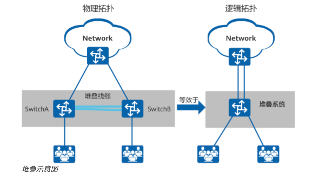
Switch stacking uses physical cables to connect two switches and combines them into a single logical forwarding device. It can increase port capacity and bandwidth while simplifying the network topology. However, stacking also has limitations. A software upgrade may interrupt services, and a stack cable failure may split the stack. A server can connect to the switch through either a single cable or multiple bonded cables.
Non-Stacking Architecture
-
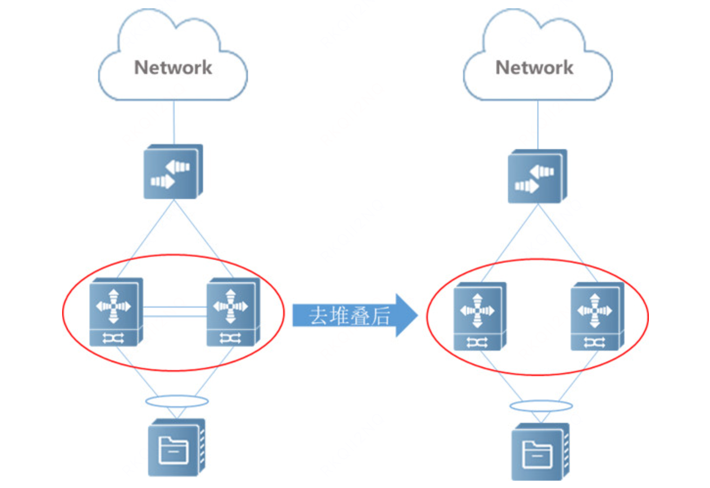
A non-stacking architecture removes the physical connection between the two switches to reduce failure risks. The server connects to two independent switches through separate links and aggregates them with LACP. Both switches must use the same system ID and different port IDs. This configuration presents the switches to the server as a single LACP peer and allows the links to form one aggregation group.
 The Linux kernel must also broadcast ARP/ND packets so that both switches receive them and can synchronize their sessions. The Linux kernel already supports this behavior:
net: bonding: add broadcast_neighbor option for 802.3ad
net: bonding: add broadcast_neighbor netlink option
net: bonding: send peer notify when failure recovery
 1
 2
 3
 4
 5
 6
 7
 8
 9
10
11
12
13
14
15
16
17
18
19
20
21
22
23
24
25
26
27
28
29
30
31
32
33
34
35
36
37
38
39
40
41
42
43
44
45
46
47
48
49
50
51
52
53
54
55
56
57
58
59
60
61
62
63
64
65
66
net: bonding: add broadcast_neighbor option for 802.3ad Stacking technology is a type of technology used to expand ports on Ethernet switches. It is widely used as a common access method in large-scale Internet data center architectures. Years of practice have proved that stacking technology has advantages and disadvantages in high-reliability network architecture scenarios. For instance, in stacking networking arch, conventional switch system upgrades require multiple stacked devices to restart at the same time. Therefore, it is inevitable that the business will be interrupted for a while. It is for this reason that "no-stacking" in data centers has become a trend. Additionally, when the stacking link connecting the switches fails or is abnormal, the stack will split. Although it is not common, it still happens in actual operation. The problem is that after the split, it is equivalent to two switches with the same configuration appearing in the network, causing network configuration conflicts and ultimately interrupting the services carried by the stacking system. To improve network stability, "non-stacking" solutions have been increasingly adopted, particularly by public cloud providers and tech companies like Alibaba, Tencent, and Didi. "non-stacking" is a method of mimicing switch stacking that convinces a LACP peer, bonding in this case, connected to a set of "non-stacked" switches that all of its ports are connected to a single switch (i.e., LACP aggregator), as if those switches were stacked. This enables the LACP peer's ports to aggregate together, and requires (a) special switch configuration, described in the linked article, and (b) modifications to the bonding 802.3ad (LACP) mode to send all ARP/ND packets across all ports of the active aggregator. Note that, with multiple aggregators, the current broadcast mode logic will send only packets to the selected aggregator(s). +-----------+ +-----------+ | switch1 | | switch2 | +-----------+ +-----------+ ^ ^ | | +-----------------+ | bond4 lacp | +-----------------+ | | | NIC1 | NIC2 +-----------------+ | server | +-----------------+ - https://www.ruijie.com/fr-fr/support/tech-gallery/de-stack-data-center-network-architecture/ Cc: Jay Vosburgh <jv@jvosburgh.net> Cc: "David S. Miller" <davem@davemloft.net> Cc: Eric Dumazet <edumazet@google.com> Cc: Jakub Kicinski <kuba@kernel.org> Cc: Paolo Abeni <pabeni@redhat.com> Cc: Simon Horman <horms@kernel.org> Cc: Jonathan Corbet <corbet@lwn.net> Cc: Andrew Lunn <andrew+netdev@lunn.ch> Cc: Steven Rostedt <rostedt@goodmis.org> Cc: Masami Hiramatsu <mhiramat@kernel.org> Cc: Mathieu Desnoyers <mathieu.desnoyers@efficios.com> Cc: Nikolay Aleksandrov <razor@blackwall.org> Signed-off-by: Tonghao Zhang <tonghao@bamaicloud.com> Signed-off-by: Zengbing Tu <tuzengbing@didiglobal.com> Link: https://patch.msgid.link/84d0a044514157bb856a10b6d03a1028c4883561.1751031306.git.tonghao@bamaicloud.com Signed-off-by: Paolo Abeni <pabeni@redhat.com> -
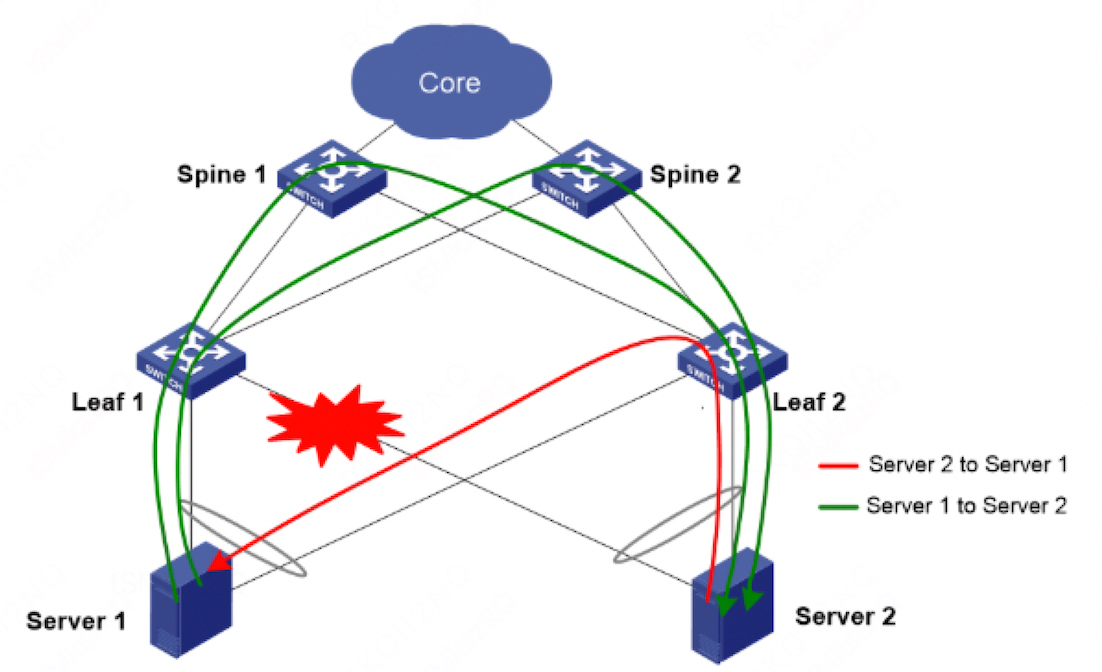
To prevent traffic black holes, all traffic must be routed through Layer 3. For example, if a physical downlink on a switch fails, the server cannot detect the failure and may continue sending data to that switch. Even communication between servers connected to the same top-of-rack (ToR) switch must traverse Layer 3. This prevents black holes caused by direct Layer 2 forwarding.
-
Layer 3 routing requires ARP/ND proxying. Both switches must also use the same gateway MAC address. Multicast must be disabled on the switches to avoid interference.
 1
 2
 3
 4
 5
 6
 7
 8
 9
10
interface Vlanif3 description K8S-Access ip address 10.0.8.1 255.255.248.0 arp timeout 90 arp proxy anyway enable mac-address 0000-8989-0001 arp delete trigger link-down enable arp direct-route enable arp direct-route delay 120 arp direct-route preference 1 -
Each switch converts the server ARP/ND entries that it learns into host routes and advertises them to upstream switches. This ensures that return traffic reaches the correct server.
-
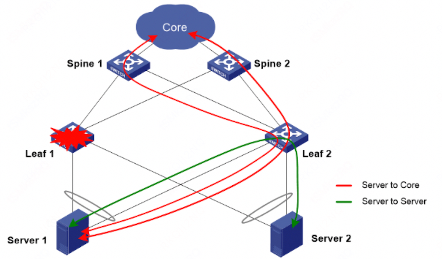
High availability requires uplink interface tracking. If all uplinks on a switch go down, the switch automatically shuts down its downlink interfaces. When an uplink recovers, the switch brings the downlinks back up after a delay. On the server, the bonding driver immediately removes a slave from the transmit set when its link goes down. After the link recovers, the slave is not enabled until LACP negotiation completes.
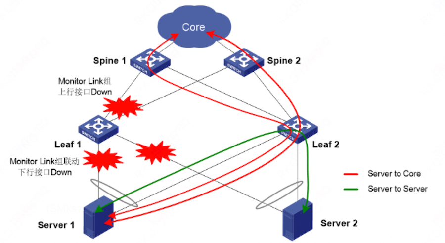
-
Fault monitoring is also required. HUATUO provides LACP and NETDEV-HW monitoring to detect failures early. In production, we have detected many LACP anomalies caused by unavailable AOCs, as well as network outages caused by packet loss in network hardware.
An AOC failure does not always produce a persistent Link Down state. The following two types of gray failure require particular attention:
- Marginal optical power: When the AOC receive power approaches the receiver sensitivity threshold, the physical layer may keep the link up while FEC corrections, CRC/FCS errors, or PCS errors continue to increase. Because the NIC carrier remains up, LACP may keep the member link in the Collecting/Distributing state. The bonding driver also continues to hash some traffic to the link, resulting in intermittent packet loss or a traffic black hole. Even if the other uplink is fully operational, it does not automatically carry traffic assigned to a failed link that is still considered available.
- Intermittent link flapping: Poor AOC seating, temperature changes, power fluctuations, or internal component failures can cause the link to alternate repeatedly between Up and Down. Each Link Down event removes the member link and moves its traffic. After recovery, the link must complete LACP negotiation before it can rejoin the aggregation group. Frequent flapping causes repeated convergence, transient packet loss, packet reordering, and TCP retransmissions. Latency-sensitive or RDMA workloads may also time out. Very short flaps can be missed when the monitoring interval is too long.
 1
 2
 3
 4
 5
 6
 7
 8
 9
10
11
12
13
14
15
16
17
18
19
20
# git clone https://github.com/ccfos/huatuo.git # ls -l huatuo/bpf/ total 84 -rw-r--r-- 1 root root 1677 Aug 11 01:44 cgroup_css_events.c -rw-r--r-- 1 root root 1450 Aug 31 22:24 cgroup_css_gather.c -rw-r--r-- 1 root root 4539 Aug 11 01:44 dropwatch.c -rw-r--r-- 1 root root 801 Aug 29 10:16 hungtask.c drwxr-xr-x 2 root root 4096 Aug 29 10:16 include -rw-r--r-- 1 root root 648 Aug 11 01:44 lacp.c -rw-r--r-- 1 root root 2155 Aug 11 01:44 memory_free_compact.c -rw-r--r-- 1 root root 1424 Aug 11 01:44 memory_reclaim.c -rw-r--r-- 1 root root 1421 Aug 11 01:44 memory_reclaim_events.c -rw-r--r-- 1 root root 1044 Sep 6 03:09 netdev_hw.c -rw-r--r-- 1 root root 4219 Aug 11 01:44 netrecvlat.c -rw-r--r-- 1 root root 1553 Sep 5 09:26 oom.c -rw-r--r-- 1 root root 1491 Aug 18 07:06 perf.c -rw-r--r-- 1 root root 8683 Aug 11 01:44 runqlat_tracing.c -rw-r--r-- 1 root root 1879 Sep 26 04:32 softirq.c -rw-r--r-- 1 root root 3429 Aug 11 01:44 softirq_tracing.c -rw-r--r-- 1 root root 1117 Aug 29 10:16 softlockup.c
Other Considerations
- The lacp edge-port feature provides a fallback for a dual-uplink network before LACP is available or its initial configuration is complete. This helps maintain network availability.
- When the source of packet loss is unclear—for example, when
tcpdumpshows that the server transmitted a packet but the switch did not receive it—configure Mirror On Drop (MOD) on the switch to assist with troubleshooting.